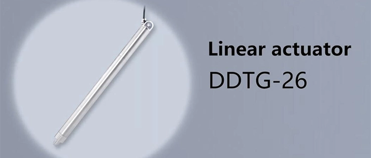
Choosing an actuator by voltage alone is one of the easiest ways to end up with the wrong motion solution. A 24 VDC power supply tells you what electrical input the equipment can provide; it does not tell you whether the actuator can handle the load, reach the required position, complete the movement fast enough, or survive the machine's operating environment.
For a 24 volt dc linear actuator, those decisions are determined by a combination of thrust, stroke, speed, duty cycle, protection rating, mounting geometry, and feedback. The right combination can look very different from one machine to another, even when both systems use the same 24V power source.
This makes actuator selection less about finding a universally “powerful” model and more about matching the actuator's mechanical and electrical characteristics to the actual job. For equipment designers and engineers, understanding these factors also makes it easier to decide whether a standard configuration is sufficient or whether a customized actuator is worth considering.
How Force and Load Requirements Determine the Right 24 Volt DC Linear Actuator
Force is usually where actuator selection becomes practical. The actuator needs to generate enough thrust to move the load reliably throughout its working cycle, but choosing the highest available force rating is not necessarily the best approach. An oversized actuator can add unnecessary cost, dimensions, and mechanical demands to a machine.
The general force range provided for these 24V actuator configurations is approximately 50–1000+ N (11–225+ lbs), depending on the model. The actual requirement, however, depends on much more than the weight of the moving component. Movement direction, friction, acceleration, mechanical leverage, external resistance, and the actuator's mounting position can all influence the required thrust.
A vertically moving load, for example, may place considerably different demands on an actuator than a horizontal positioning mechanism. A machine that repeatedly starts and stops under load may also require a different configuration from one that moves a component slowly and occasionally.
Jointway Leader's customization information extends beyond the general product range. Standard force configurations are described from approximately 200 N to 15,000 N, while customized designs can reach up to approximately 30,000 N for demanding applications. At the other end of the range, low-force configurations can be considered where controlled, delicate movement is more important than high thrust.
These figures should be understood as application-dependent capabilities rather than a single standard range for every 24 volt dc linear actuator. When evaluating an actuator, engineers should provide the expected working load, peak load, movement direction, and operating cycle so that the required force can be assessed realistically.
This information is particularly useful when comparing 24 volt linear actuator suppliers. A supplier that understands the complete load condition can help distinguish between a suitable actuator and one that only appears adequate based on its nominal force rating.
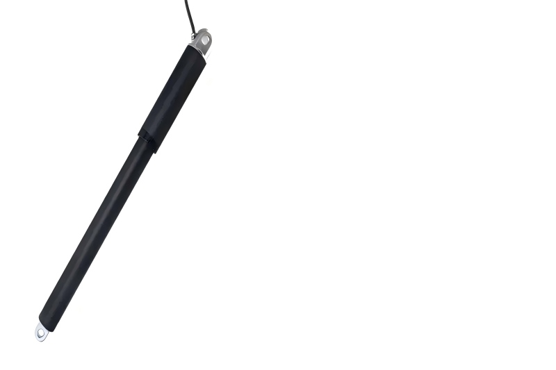
Choosing the Right Stroke Length and Speed for Industrial Motion
Stroke length answers a simple question: how far does the actuator need to move? Speed answers another: how quickly must it get there? In industrial equipment, these two specifications are closely related because together they determine whether the actuator can complete the required movement within the machine's operating cycle.
The general 24V specifications provided for this product category cover stroke lengths of approximately 50–500+ mm (2–20+ inches) and speeds of about 2–20 mm/s (0.08–0.8 in/s), depending on the model.
Choosing a longer stroke simply because it provides more movement is rarely necessary. If a mechanism only needs 100 mm of travel, a substantially longer actuator can consume additional installation space without improving performance. The opposite problem occurs when the selected stroke is too short: the actuator may reach its physical limit before the mechanism reaches its required position.
Speed needs to be considered under the actual working load as well. A specification such as 20 mm/s does not necessarily mean that the actuator will maintain that speed under every load condition. Motor characteristics, screw design, gearing, stroke, and load can all influence actual operating speed.
For applications outside standard configurations, Jointway Leader's customization information indicates that stroke lengths can be adapted from approximately 20 mm to as much as 3,000 mm, depending on the actuator design. This creates more flexibility for applications ranging from compact adjustment mechanisms to longer-travel industrial positioning systems.
The most useful starting point is therefore the movement requirement of the machine: determine the required travel, available installation space, load, and acceptable movement time before selecting the actuator model.
Why Duty Cycle and Operating Conditions Matter in Actuator Selection
An actuator that works perfectly in an occasional adjustment mechanism may not be suitable for equipment that operates it repeatedly throughout the day. The difference is often found in the duty cycle.
The supplied specifications indicate duty-cycle options from approximately 25% to 100%, depending on the model and operating conditions. Duty cycle should be considered alongside load rather than treated as an isolated number. Repeated movement under a heavy load can generate substantially more thermal and mechanical stress than occasional movement under a light load.
Consider how the actuator will actually be used. How many times will it extend and retract during an operating period? How long does each movement take? How much time is available between cycles? Does the actuator remain loaded while stationary? These details can change the suitability of a particular model.
Temperature is another variable that should be established before selecting the actuator. The general operating temperature range provided for these configurations is approximately -20°C to +60°C (-4°F to 140°F). If equipment operates outside this range, the actuator should be evaluated specifically for those conditions rather than assuming that the standard specification applies.
Outdoor machinery, agricultural equipment, and equipment installed near heat-generating processes can experience considerable temperature variation. In such cases, the actuator's seals, lubrication, electronic components, and materials may all need to be considered alongside the basic motor and thrust specifications.
Matching Protection Ratings and Materials to the Working Environment
The environment surrounding an actuator can be just as important as the load it moves. Dust, moisture, water, chemicals, salt spray, and abrasive particles can gradually affect mechanical and electrical components if the actuator is not designed for the application.
Depending on the model, the available protection ratings include IP54, IP65, and IP67. These ratings provide different levels of protection against dust and water ingress. The appropriate choice should be based on the actual conditions at the installation point rather than on the assumption that the highest rating is always the most suitable.
Material selection can provide another layer of protection. Jointway Leader's customization information includes 316 stainless steel for marine and corrosive environments, anodized aluminum for applications where weight and durability need to be balanced, and polymer-coated rods for situations where abrasion resistance is important.
For marine equipment, corrosion from saltwater may be a major concern. Agricultural machinery may face moisture, mud, and outdoor exposure, while mining and construction equipment can expose actuators to dust and abrasion. Each environment creates a different combination of requirements.
For this reason, IP protection should not be evaluated in isolation. Cable entry, seals, exposed mechanical components, material compatibility, operating temperature, and mounting position can all influence actuator reliability. The goal is to select a 24 volt dc linear actuator whose complete construction matches the environment in which it will operate.
Selecting Mounting and Feedback Options for Better Equipment Integration
An actuator can have the correct force and stroke and still perform poorly if it is installed incorrectly. Mechanical alignment determines how the actuator transfers force to the machine, and excessive side loading can place unnecessary stress on the actuator's rod, bearings, screw mechanism, and mounting points.
Depending on the design, mounting options can include flange, bracket, threaded-rod, clevis, and trunnion arrangements. A clevis configuration can be useful when the actuator needs to pivot with a moving mechanism, while a flange or fixed bracket may be better suited to equipment where the actuator remains in a defined position.
Installation space should be checked before selecting the actuator. The retracted length, extended length, mounting distance, bracket position, and available clearance all need to work with the machine's mechanical layout. When standard dimensions do not fit, customized brackets or mounting arrangements can eliminate the need for major changes to the equipment.
Feedback requirements should be considered at the same stage. Limit switches can establish end positions, while potentiometers and Hall-effect sensors can provide position information. Encoder-based feedback may be considered when an automated system needs more detailed position monitoring.
The right feedback option depends on the control architecture. A simple lifting mechanism may only need end-of-stroke detection, while an automated production system may require position information that can be processed by a PLC or another controller.
This is also an important point when comparing 24 volt linear actuator suppliers. The ability to discuss mounting dimensions, brackets, feedback, wiring, and control requirements can be just as valuable as the ability to supply the actuator itself.
| Selection Parameter | Typical Specification Range | Key Selection Consideration |
|---|
| Voltage | 24 VDC | Confirm compatibility with the equipment's power supply. |
| Force/Thrust | 50–1000+ N | Match the working and peak load requirements. |
| Stroke Length | 50–500+ mm | Match the required travel and available installation space. |
| Speed | 2–20 mm/s | Evaluate the required movement time under the expected load. |
| Duty Cycle | 25–100% | Consider operating frequency, movement duration, and rest periods. |
| Protection Rating | IP54, IP65, IP67 | Match protection to dust, moisture, water, and outdoor exposure. |
| Mounting Options | Flange, bracket, threaded rod, and other configurations | Check mechanical alignment and available installation space. |
| Feedback Options | Potentiometer, Hall Effect sensor, limit switches | Select according to positioning and control requirements. |
| Operating Temperature | -20°C to +60°C | Confirm compatibility with the actual working environment. |
When Standard Specifications Are Not Enough: Customizing a 24 Volt DC Linear Actuator
Standard actuator specifications work well for many machines, but industrial equipment does not always conform to standard dimensions. A mechanism may need a particularly short or long stroke, greater thrust, a specialized bracket, specific feedback, or materials suited to a corrosive environment.
Customization becomes useful when these requirements cannot be met by an existing configuration. Rather than redesigning the machine around an actuator that is only approximately suitable, the actuator can be adapted to the actual requirements of the equipment.
Stroke is one of the clearest examples. The supplied customization information indicates that designs can be developed from approximately 20 mm to as much as 3,000 mm, depending on the application and actuator structure. A compact stroke may be appropriate for medical or laboratory mechanisms, while longer travel can be useful for solar tracking and specialized industrial positioning systems.
Force can be customized as well. The general product information covers approximately 50–1000+ N, while the stated customization capability extends from low-force configurations around 50 N to high-force designs of up to approximately 30,000 N. Such a range allows the actuator to be considered for applications with very different mechanical demands.
Mounting can be adapted when the equipment has unusual spatial constraints. Clevis, trunnion, flange, and custom bracket configurations can be considered according to how the actuator needs to move and where it can be installed. Wire length and other installation details may also be adapted for system integration.
Control and feedback requirements can be addressed during the same process. Depending on the design, the supplied product information includes potentiometer, Hall-effect, and encoder feedback options, as well as analog and digital interfaces and CAN Bus integration for suitable applications.
Material selection can also be tailored to the environment. 316 stainless steel can be considered for marine or corrosive conditions, anodized aluminum where weight and durability are important, and polymer-coated rods where abrasion resistance is required.
Customization works best when the technical requirements are clearly defined from the beginning. Load, stroke, speed, duty cycle, installation dimensions, ambient temperature, exposure conditions, feedback, control interface, and power supply all provide useful information for evaluating the right configuration.
Once these requirements are clear, engineers can review Jointway Leader's linear actuator product range to compare available configurations and see which models are closest to the application's needs. When the requirements involve non-standard force, stroke, mounting, materials, feedback, or control functions, the application details can be discussed through the Jointway Leader contact page to determine whether a standard or customized solution makes more sense.
Conclusion
Selecting a 24 volt dc linear actuator for industrial equipment is not simply a matter of matching the actuator to a 24V power supply. The mechanical requirements determine whether it can move the load, the stroke and speed determine whether it can perform the required movement, and the duty cycle determines whether it can sustain the expected operating pattern.
Environmental conditions add another layer to the decision. IP protection, material selection, and operating temperature should reflect the conditions around the actuator, while mounting and feedback need to work with the machine's mechanical and control architecture.
When standard specifications are close but not quite right, customization can bridge the gap through changes to force, stroke, mounting, feedback, materials, wiring, or control interfaces. By defining these requirements before selecting a model, equipment designers can compare options more efficiently and work more productively with 24 volt linear actuator suppliers.
The best actuator is not necessarily the largest, fastest, or most heavily protected option. It is the configuration that matches the actual job without introducing unnecessary capacity or compromising reliability.
FAQ
1. What is a 24 volt dc linear actuator used for?
A 24 volt dc linear actuator converts electrical energy into controlled linear movement. It can be used for lifting, pushing, pulling, positioning, and adjustment in industrial automation, robotics, medical equipment, solar tracking systems, agricultural machinery, and other applications.
2. What force range is available for a 24V linear actuator?
The general specification range provided for these 24V actuator configurations is approximately 50–1000+ N. Higher-force customized configurations can be developed for applications that require substantially greater thrust.
3. How should I choose the correct stroke length?
The stroke should correspond to the actual distance the machine needs to move while fitting within the available installation space. A stroke that is too short limits movement, while an unnecessarily long stroke can increase installation requirements.
4. Does actuator speed remain constant under different loads?
No. Actual speed can vary according to load, actuator design, stroke, motor configuration, and operating conditions. The required speed should be evaluated under the expected working load.
5. Which protection rating should I choose?
IP54, IP65, and IP67 configurations are available depending on the model. The appropriate rating depends on exposure to dust, moisture, water, and other environmental conditions. Material selection should also be considered for corrosive or abrasive applications.
6. When should I consider a customized 24 volt dc linear actuator?
Customization is useful when standard force, stroke, mounting dimensions, feedback, materials, wiring, control interfaces, or environmental specifications do not meet the equipment requirements. Providing complete application information helps 24 volt linear actuator suppliers determine whether a standard or customized configuration is more appropriate.
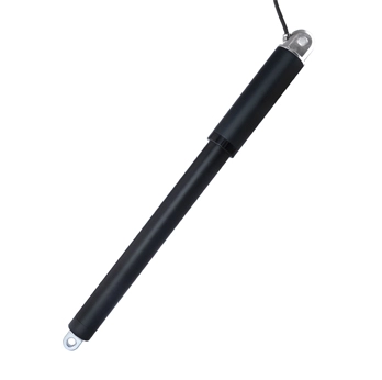
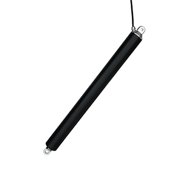
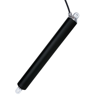
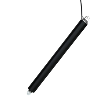

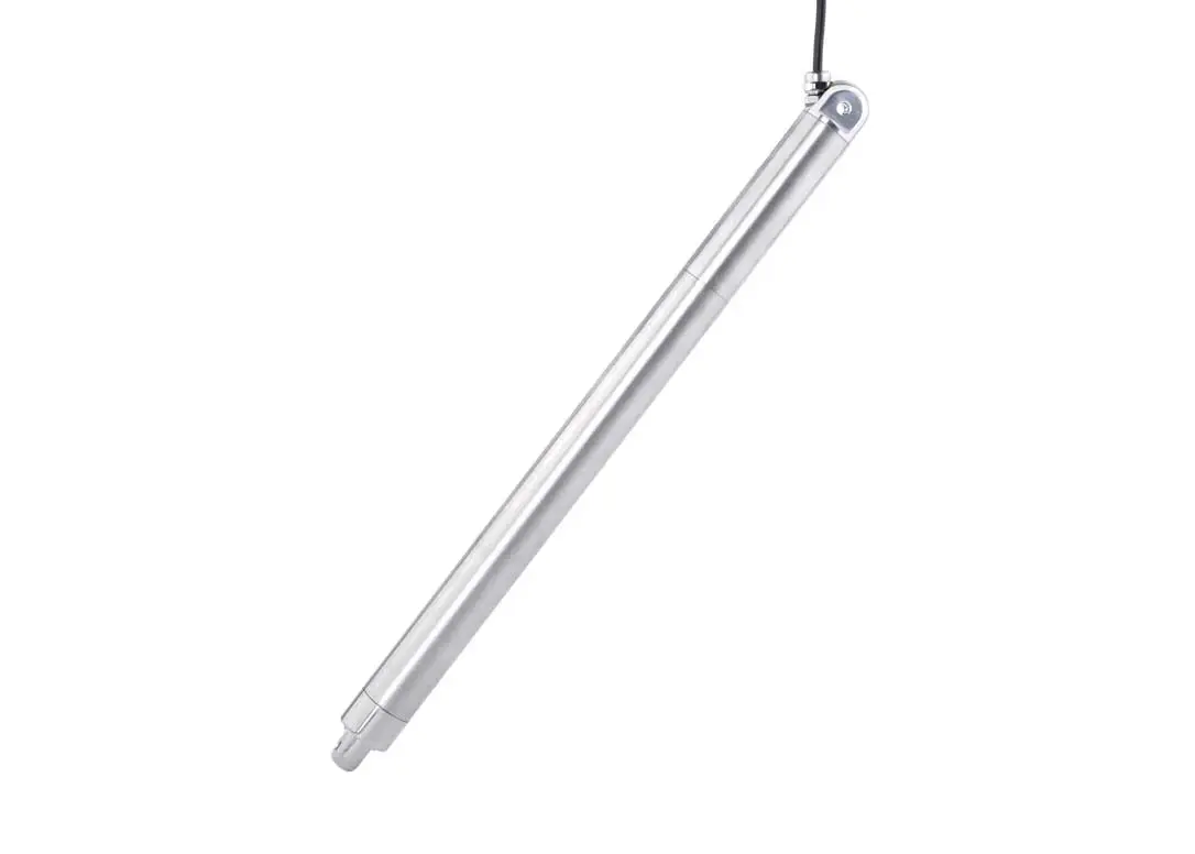

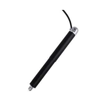 DDTG-16 Micro Tubular Linear Actuator
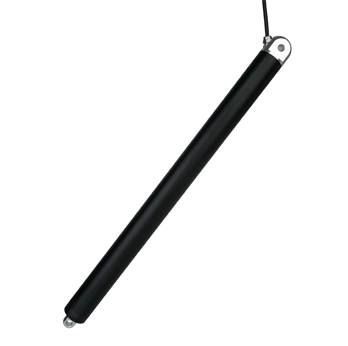
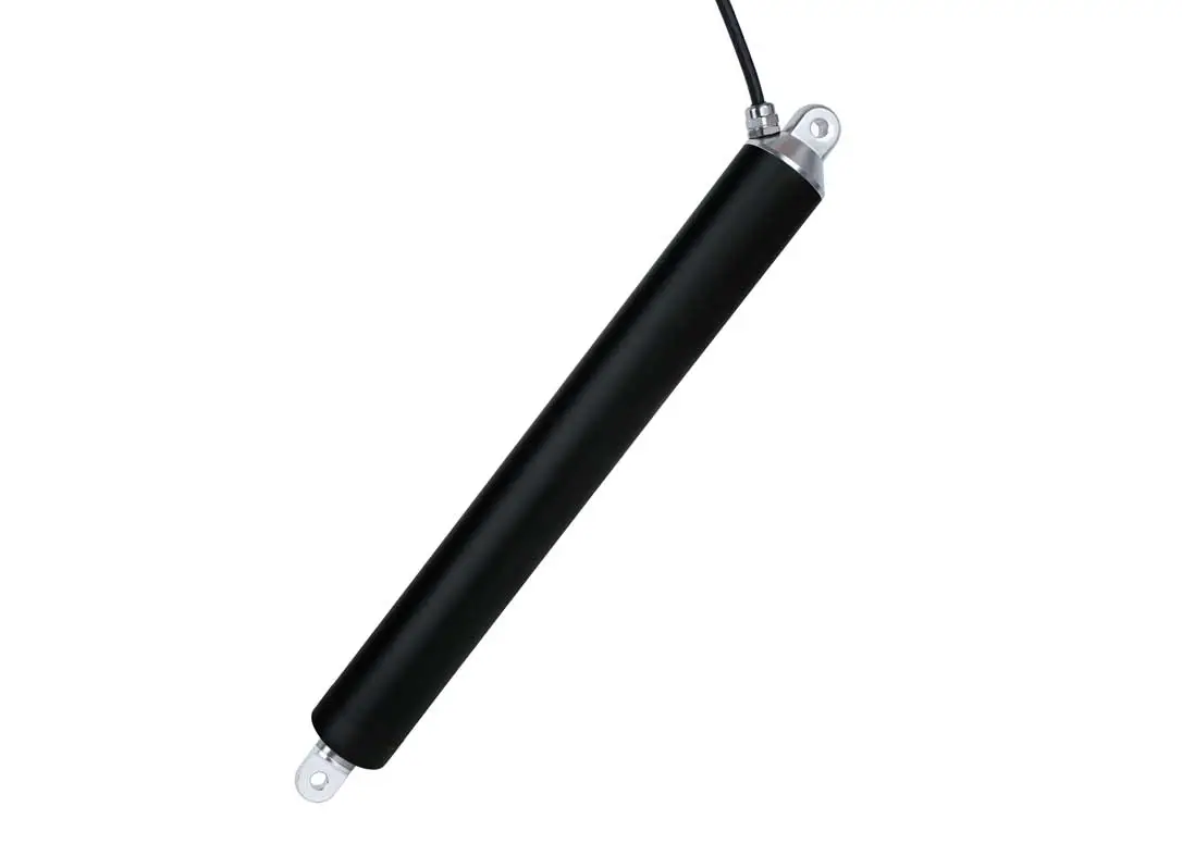
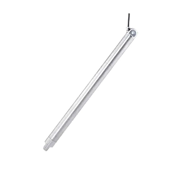 DDTG-28 Micro Tubular Linear Actuator
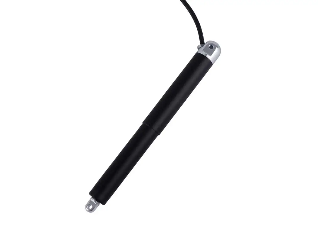
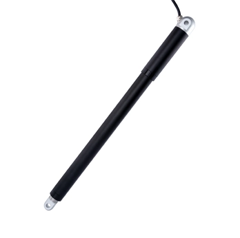 DDTG-38 Micro Tubular Linear Actuator