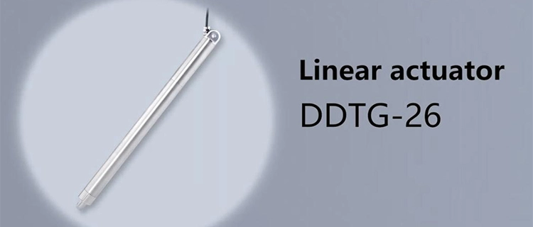
A machine does not need to move far to need precise motion. In many compact mechanisms, the critical movement may be only a small change in height, a short shift for alignment, or a controlled adjustment of a component. The challenge is making that small movement happen at the right time, by the right distance, and with enough consistency to be repeated throughout the machine's operating cycle.
This is where a micro linear actuator becomes more than a miniature motion component. When connected to an appropriate control system, a micro electric actuator can replace manual adjustment with a defined linear movement, allowing compact equipment to reposition components without adding a large mechanical drive system.
The real engineering question, however, is not simply whether a micro actuator can move a component. It is whether the actuator can provide the required stroke and force, reach the intended position consistently, fit within the available space, and work reliably with the machine's sensors and controls. Understanding these relationships is the key to using micro linear actuators effectively in automated adjustment and positioning systems.
How Micro Linear Actuators Turn Small Linear Movements into Repeatable Adjustments
Many automated machines do not require long travel distances. Instead, they need a component to move a relatively short distance and return to that position repeatedly. Examples include repositioning a fixture, adjusting the height of a mechanism, aligning a component, or changing the position of a sensor.
Traditionally, these adjustments could be made manually with a threaded mechanism, knob, slide, or similar mechanical arrangement. Such methods can work well for occasional setup, but they become less convenient when the position needs to change frequently or as part of an automated sequence. A micro linear actuator provides an electrical means of producing the required linear movement without requiring an operator to make every adjustment.
The actuator's movement is only one part of the mechanism. The connection between the actuator and the moving component also influences the result. A poorly supported load, excessive friction, or an unsuitable guide can introduce resistance or unwanted movement. The mounting structure needs enough rigidity to transfer actuator force efficiently, while the moving component should be guided in the intended direction.
Repeatability is particularly useful when the same adjustment occurs throughout a production cycle. Once the required movement has been established, a micro electric actuator can receive commands from the machine's control system and perform the adjustment as part of the programmed sequence. This reduces reliance on manual intervention and makes the movement easier to coordinate with other machine functions.
The objective is not simply to use the smallest actuator available. The actuator still needs enough force to move the load, sufficient stroke to complete the adjustment, and an appropriate operating speed for the machine. Its dimensions should also fit the available installation space without compromising the mechanical connection.
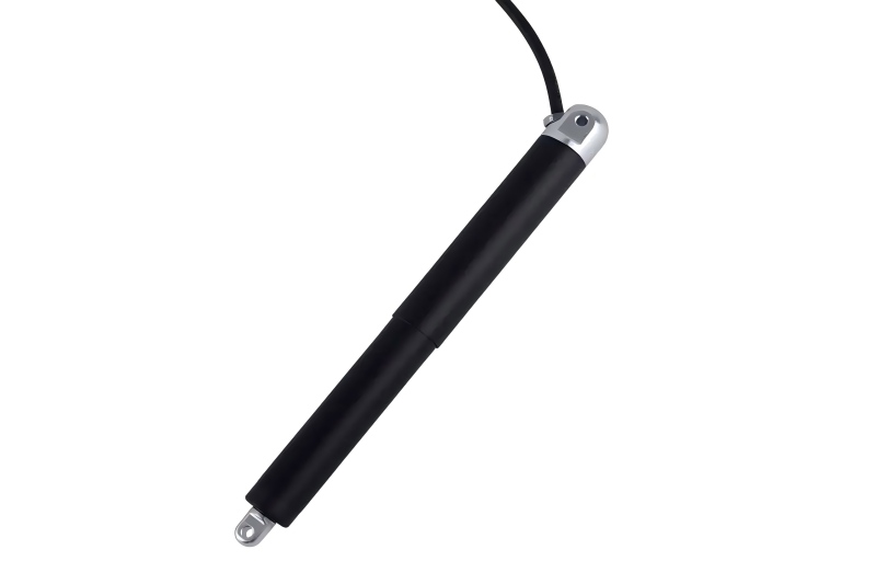
Balancing Stroke, Force, and Speed for Accurate Positioning
Stroke, force, and speed are often listed as separate actuator specifications, but they are closely related when the actuator is installed in real equipment. The required movement determines the stroke, the mechanical resistance determines the force requirement, and the desired cycle time determines how quickly the movement needs to take place.
Stroke should be based on the actual range of adjustment. An actuator with insufficient stroke cannot complete the required movement, while unnecessarily long travel can complicate installation and increase the space required for the mechanism. The actuator also needs to remain mechanically supported throughout its complete travel.
Force is not determined by the weight of the moving component alone. Friction, spring resistance, linkage geometry, external forces, and the way the load is supported can all affect the force required. A lightweight component may therefore require more actuator force than its mass initially suggests.
Speed introduces a further consideration. A faster micro linear actuator can reduce adjustment time, but rapid movement may increase vibration or make the mechanism more difficult to stop smoothly. This becomes more noticeable when the load has significant inertia or when the actuator is connected to a flexible structure.
| Requirement | Effect on the Motion System | What to Check |
|---|
| Stroke | Defines the available linear travel | Required adjustment range and installation space |
| Force | Determines whether the actuator can move and hold the load | Load mass, friction, spring force, and linkage geometry |
| Speed | Influences adjustment time and dynamic behavior | Required cycle time and acceleration/deceleration |
| Mounting | Affects how actuator movement is transferred to the load | Alignment, support structure, and load connection |
| Duty cycle | Influences operating temperature and mechanical stress | Movement frequency and expected operating pattern |
These factors should be evaluated together when choosing a micro electric actuator. A model that looks suitable based on force alone may not be appropriate once stroke, speed, mounting space, and operating frequency are considered.
Engineers can review the available micro linear actuator and linear actuator according to the movement requirements of the equipment rather than selecting a model based on a single specification.
When Position Feedback Matters for Micro Linear Actuator Positioning
Not every automated adjustment mechanism requires continuous position feedback. In a simple system, the actuator may only need to move between two known positions, making limit switches or other end-of-travel controls sufficient for the application.
The situation changes when the machine needs to reach different positions during operation or when the actual position of the load needs to be monitored. A position sensor or encoder can provide information to the controller, allowing it to determine whether the commanded movement corresponds to the actual movement.
This can be useful when load conditions vary or when the mechanism needs to make repeated adjustments at different positions. Feedback can also help identify movement that does not match the expected response, although it cannot correct every mechanical problem by itself.
Encoder resolution should therefore not be confused with overall positioning accuracy. A high-resolution encoder may detect very small changes in position, but mechanical backlash, structural deflection, friction, or misalignment can still affect where the load actually stops.
The location of the feedback device also deserves attention. Monitoring motor rotation does not necessarily provide the same information as measuring the actual position of the driven component. Where the feedback is placed should depend on the mechanical arrangement and the level of positioning control required.
For a micro linear actuator, feedback is most useful when it solves a specific control problem. Adding sensors simply because they are available can increase system complexity without necessarily improving the final result.
Connecting the Actuator with Sensors and Motion Controls
A micro electric actuator becomes part of a larger motion system once it is connected to sensors and a controller. The actuator creates the physical movement, while the control system determines when that movement should occur, where it should stop, and how it should interact with other machine functions.
Limit switches can establish travel boundaries and prevent the mechanism from moving beyond its intended range. Position sensors can provide information about the current location of the moving component. The controller can then use these signals to coordinate actuator movement with the rest of the equipment.
The required control arrangement depends on how the actuator is used. A mechanism that makes one adjustment during machine setup may only need a simple control signal. A mechanism that continuously changes position as part of a production sequence may require more sophisticated control and feedback.
Motion timing is another consideration. The controller may need confirmation that the actuator has reached its required position before another operation begins. If the next machine action starts before the mechanism has settled, the actuator may be mechanically capable of reaching the target while the overall process still produces an inaccurate result.
Electrical and mechanical compatibility should also be checked before integration. Voltage, control method, mounting dimensions, stroke, operating conditions, and feedback requirements all need to fit the architecture of the equipment.
In practice, this means the actuator should be selected at the same time as the basic control strategy. Treating the actuator as a separate component and trying to determine its control method after installation can create unnecessary integration problems.
Where Micro Linear Actuators Make Automated Adjustment More Practical
The strongest use cases for a micro linear actuator are often mechanisms that require controlled movement but have limited space for conventional drive components. The movement itself may be small, yet the ability to automate that movement can simplify the overall equipment design.
Automated equipment adjustment is one example. A machine may need to reposition a component when product dimensions or operating conditions change. Instead of stopping the equipment for manual adjustment, an actuator can move the component according to a command from the control system.
Alignment is another useful application. Sensors, fixtures, optical components, and other small machine elements may need controlled movement to reach a defined position. In these cases, compact dimensions and predictable linear travel can be more useful than high output force.
Micro linear actuators can also be incorporated into compact mechanisms where the available installation space makes a larger actuator impractical. Their small form factor allows designers to add linear movement without significantly increasing the size of the surrounding equipment, provided that the required load and stroke remain within the actuator's capabilities.
The same principle applies to adjustment mechanisms that would otherwise require repeated manual intervention. When the machine needs to make the same type of movement many times, converting that movement into an electrical command can make the operation more consistent and easier to coordinate with other processes.
Jointway Leader's actuator solutions can be evaluated according to these actual application requirements. If the required stroke, load, speed, mounting arrangement, duty cycle, or control method is not straightforward, engineers can discuss their micro electric actuator requirements before finalizing the mechanism. This allows the actuator configuration to be considered alongside the machine rather than as an isolated component.
Conclusion
A micro linear actuator can make a small mechanical adjustment repeatable, controllable, and suitable for integration into an automated process. Its usefulness comes from the relationship between compact size and controlled linear movement, but the actuator itself is only one part of the final positioning system.
Stroke, force, speed, mounting conditions, load characteristics, feedback, sensors, and motion control all influence how effectively the actuator performs its intended task. Simple applications may only require basic end-position control, while more demanding positioning systems may benefit from feedback and coordinated motion control.
For equipment designers, the most reliable approach is to define the actual movement first and then match the micro electric actuator to that requirement. When the actuator, mechanical structure, sensors, and controller are considered as one system, automated adjustment becomes easier to implement and more consistent in operation.
FAQ
1. What is a micro linear actuator used for?
A micro linear actuator is used to create controlled linear movement in compact mechanisms, including automated adjustment, positioning, alignment, and small equipment mechanisms.
2. How does a micro electric actuator automate adjustment?
It converts an electrical command into linear movement, allowing a controller to reposition a component without requiring manual adjustment.
3. Does every micro linear actuator need position feedback?
No. Simple end-position applications may only need limit switches, while applications requiring variable or more controlled positioning may benefit from feedback sensors.
4. How do stroke and force affect actuator performance?
Stroke determines how far the actuator can move, while force determines whether it can overcome the load and other mechanical resistance.
5. Can a micro electric actuator work with sensors?
Yes. Depending on the configuration, sensors such as limit switches or position feedback devices can be integrated into the actuator control system.
6. What should be checked before selecting a micro linear actuator?
Consider the required stroke, load, speed, mounting space, duty cycle, control method, feedback requirements, and the mechanical conditions of the equipment.
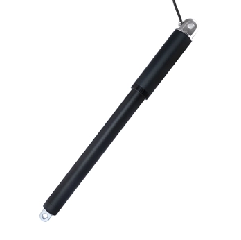
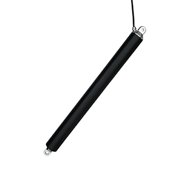
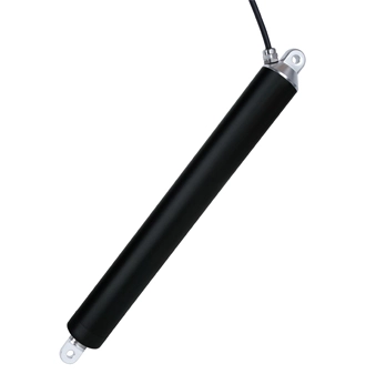
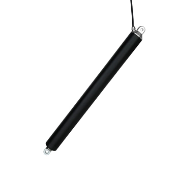

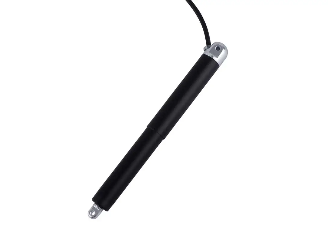
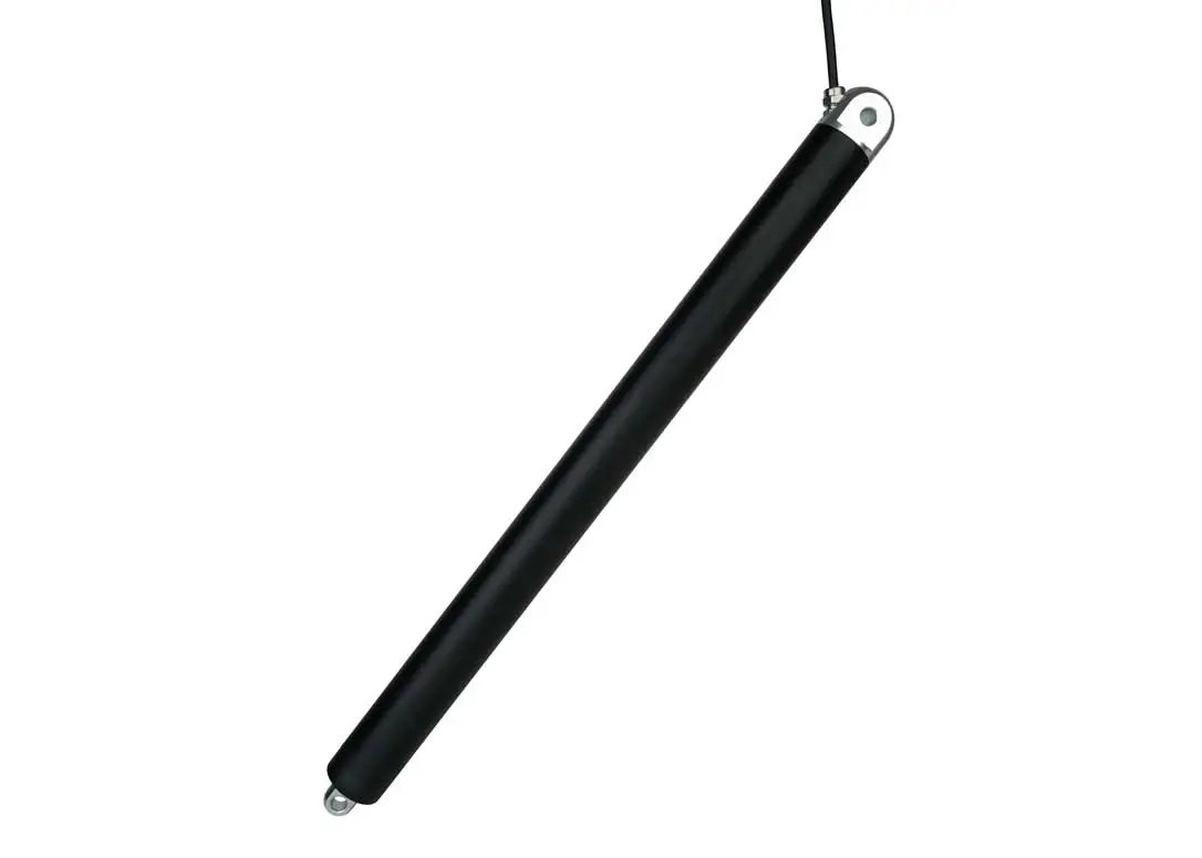
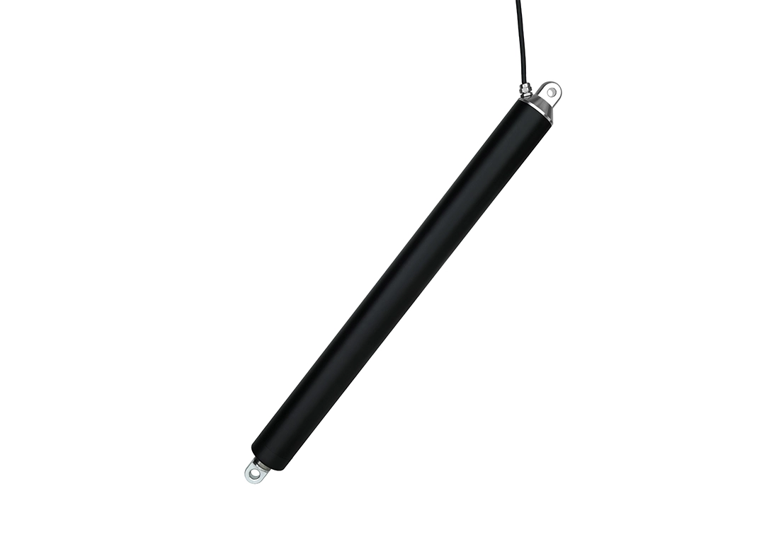
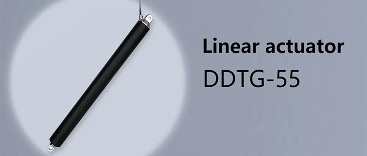

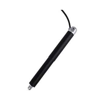 DDTG-16 Micro Tubular Linear Actuator
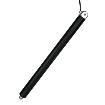
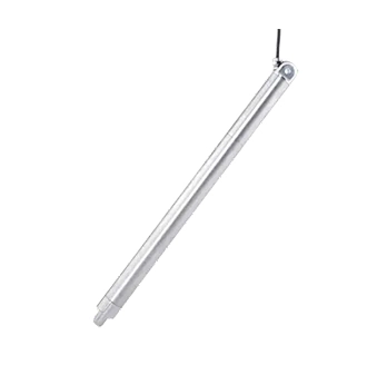 DDTG-28 Micro Tubular Linear Actuator
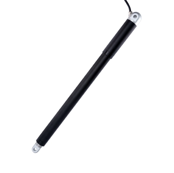 DDTG-38 Micro Tubular Linear Actuator